
Home › Products › Flanges › JIS square flanges
RFS · ready stockJIS square flanges to B2291 & F7806, 1/4" to 6"
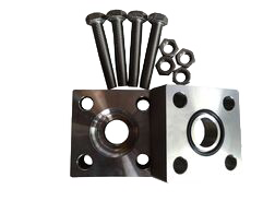
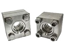
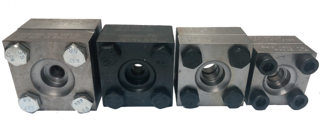
The four‑bolt square socket‑weld connection, 1/4" to 6", in 210, 280 and 350 kgf/cm². Forged SF440A steel or stainless SS316, in SHA/SHB, SSA/SSB, KA/KB and LSA, weld‑in or blind — supplied as complete sets, both halves with the O‑ring, bolts and nuts, from stock in Malaysia and Singapore. Full dimension, bolt and O‑ring tables for all three series, below — straight from the JIS drawings.
Get a quotation within 2 working hours
Send the part number, standard, size or quantity. Stock in Malaysia or Singapore, ISO 9001:2015 certified.
What a JIS square flange is, and when you need one
A different family from the SAE four‑bolt flange — not a variation on it.
A square flange joins pipe to pipe or pipe to component in a hydraulic system. The body is square rather than round, the four bolts pass through the corners, and an O‑ring in a machined groove does the sealing — not metal‑to‑metal contact. The result is a compact, high‑pressure joint that can be broken and remade without disturbing the pipe run.
The family that matters in this region is Japanese. Square flanges are made to national standards, and the JIS pattern is what turns up on Japanese and Korean‑built machinery, shipboard hydraulics, offshore structures and palm oil mill plant across Malaysia and Singapore. If you are matching an existing installation, the standard on the flange decides everything else — so that is where this page starts.
Not the same thing as an SAE flange
| JIS square flange | SAE J518 / ISO 6162 | |
|---|---|---|
| Body | Square | Round |
| Bolts | Four through the corners | Four on a rectangle, either side of the bore |
| Seal | O‑ring in a face groove | O‑ring in a face groove |
| Rated in | kgf/cm² — 210K / 280K / 350K, rated 21 / 28 / 35 MPa | psi classes — Code 61, Code 62 |
| Sized in | Millimetres, nominal bore in A sizes — B is the inch figure | Inches |
| Handed halves | Yes, and lettered — A is the O‑ring side, B the flat side | Yes, but unlettered — ordered by code, size and end connection |
| Standard | JIS B2291 hydraulic · JIS F7806 marine | SAE J518, dimensionally the same connection as ISO 6162 |
| Where you meet it | Japanese and Korean‑built machinery, shipboard hydraulics, offshore and palm oil mill plant | Pump, motor and valve ports worldwide |
| Interchangeable | No — not in any size | No — not in any size |
The seal row is the same on both sides, and that is exactly why the two get confused. Everything else differs. We stock both lines — see SAE flanges.
Specification
Everything that has to be on the enquiry, in one table.
| Property | Specification |
|---|---|
| Size | 1/4" to 6" · 8A to 150A also written 1/4B to 6B — B is the inch figure. Most movement is 1/2" to 2" |
| Standard | JIS B2291 (hydraulic) · JIS F7806 (marine) |
| Pressure series | 210 kgf/cm² · 280 kgf/cm² · 350 kgf/cm² |
| Configuration | SHA/SHB · SSA/SSB · KA/KB · LSA A = O‑ring side, B = flat side |
| Type | Weld‑in (socket weld) · blind |
| Material | Forged steel SF440A to JIS G3201 · stainless SS316 |
| Bolts and nuts | Hex bolts SCM435 (JIS G4105), nuts S45C (JIS G4051) — four of each |
| O‑ring | NBR HS90 to JIS B2401‑1B, G and P series |
| Pipe schedule | Bore machined for SCH 40, 80 or 160 |
| Complete set | A half, B half, O‑ring, four bolts and four nuts |
Three things pin a square flange down: the nominal size in A, the pressure series in kgf/cm², and the type letter — A is the O‑ring side, B is the flat side. Give us those three and the schedule of the pipe, and there is nothing left to guess.
Buying square flanges in Malaysia and Singapore
Where the stock sits, and where the JIS pattern actually turns up in this region.
Stock, delivery and ordering
- Where the stock is — the office is in Kuala Lumpur, and flanges are held in two warehouses: Johor Bahru and Singapore. Addresses and direct lines are on the contact page.
- Dispatch — stock items leave the same or next working day, as assembled pairs with the O‑ring and bolts.
- Delivery within Malaysia — 3 to 5 working days after dispatch.
- Delivery cost — already inside the product price, along with transport, currency conversion, duties and taxes. Nothing is added afterwards.
What moves where. Singapore is shipyard and offshore work — JIS F7806, 280K or 350K KA/KB, increasingly SS316 for deck and splash‑zone lines; Japanese and Korean‑built vessels are why the pattern is on so many Singapore repair jobs. Malaysia is palm oil mills, presses and general plant — mostly 210K SHA/SHB in carbon steel to JIS B2291.
How a square flange enquiry runs
Seven things and we can price it without going back and forth:
- Size — 1/4" to 6", or the A size. B is simply the inch figure, so ½B = ½" = 15A.
- Series — 210K, 280K or 350K. It changes the whole flange, not just the rating.
- Type letter — SHA/SHB, SSA/SSB, KA/KB or LSA. A is the O‑ring side, B the flat side, and they are ordered as a pair.
- Weld‑in or blind.
- Material — forged SF440A steel or SS316.
- Pipe schedule — SCH 40, 80 or 160, so the socket bore matches your pipe.
- The application — hydraulic (B2291) or marine (F7806); on classed work, say whose paperwork the order must satisfy.
A product specialist prices it within two working hours. Matching something already fitted? Send a photo of the marking, or a rule across the bolt centres, and we will identify it. We also hold the pipe and fittings the flange joins.
JIS B2291 vs JIS F7806
Two standards, two worlds — and the one on your flange is not a detail.
JIS B2291 — hydraulic use
The hydraulic square flange standard. Sturdy construction, tight dimensional tolerances and an O‑ring face, for connecting pipe and tube inside a hydraulic circuit where the duty is pressure.
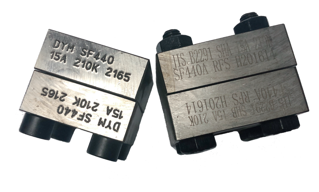
This is what you meet on machinery, presses, mill plant and mobile equipment. Our 210 kgf/cm² SHA/SHB range is marked to it — you can read JIS B2291 on the flange itself in the photo below.
JIS F7806 — marine use
The shipbuilding square flange standard, written for piping onboard ships and on offshore structures, where the duty is pressure and a salt atmosphere.
Robust construction for conditions at sea. Our 280 and 350 kgf/cm² KA/KB ranges follow it. If the job is a shipyard or an offshore one, this is usually the standard on the drawing. F7806 itself carries the warning: where these flanges go into equipment essential to the ship’s safety or propulsion, confirmation has to be obtained from the classification society or other relevant party — so the paperwork is part of the specification, not an afterthought.
They are different standards, not different grades of the same thing. Both give a square four‑bolt O‑ring joint, but the dimensions and the pressure series differ. Fit a B2291 half against an F7806 half and, at most sizes, the bolt holes will not even line up — see the identification table.
Square flange pressure series — 210K, 280K or 350K?
The number is the nominal pressure in kgf/cm² — and it changes the whole flange, not just the rating plate.
| 210K | 280K | 350K | |
|---|---|---|---|
| Nominal pressure | 210 kgf/cm² | 280 kgf/cm² | 350 kgf/cm² |
| Rated max working pressure | 21 MPa · 210 bar | 28 MPa · 280 bar | 35 MPa · 350 bar |
| Where that figure is stated | JIS B2291, titled 21 MPa | JIS F7806 table 1 | JIS F7806 table 1 |
| Type letters | SHA/SHB and SSA/SSB | KA/KB | KA/KB |
| Size range held | 1/2" to 4" 15A–100A | 1/2" to 4" 15A–100A | 1/2" to 3" 15A–80A only |
| Material | SF440A | SF440A | SF440A |
| Reference standard | JIS B2291 | JIS F7806 | JIS F7806 |
| Where it turns up | General hydraulics, mill and plant | Shipboard and offshore piping | The high‑pressure end of marine work |
The MPa figure is the standard’s own, not a unit conversion. JIS B2291 is titled 21 MPa slip‑on welding pipe flanges for hydraulic use, and JIS F7806 table 1 states the maximum working pressure as 28 MPa for 280K and 35 MPa for 350K. So the three series are rated 21, 28 and 35 MPa — 210, 280 and 350 bar. Converting the kgf/cm² label arithmetically instead understates all three, and a drawing calling for a hard 21 MPa is met by a 210K flange. Tell us the actual working pressure and we will say which series covers it.
350K stops at 80A. There is no 100A in the 350 kgf/cm² series. Above 80A at that pressure the answer is a different connection, and it is worth a conversation before the drawing is issued rather than after.
Which square flange should I start from?
| The duty | Start from | Why |
|---|---|---|
| Machinery, presses and mill hydraulics | 210K SHA/SHB to B2291 | What Malaysian palm oil mills and general plant actually run |
| Shipboard and offshore piping | 280K KA/KB to F7806 | The marine standard — written for pressure plus a salt atmosphere |
| The high‑pressure end of marine work | 350K KA/KB | 35 MPa — and it stops at 80A |
| A drawing calling for a hard 21 / 28 / 35 MPa | 210K / 280K / 350K | The MPa ratings are the standards’ own figures, not conversions |
| Replacing what is fitted | Whatever the marking says | The installed standard decides — read the marking first |
The type letters, decoded
| Type | What it is |
|---|---|
| SHA / SHB | The 210K pair to JIS B2291 — hex bolts to JIS B1180/B1182 |
| SSA / SSB | The 210K pair on socket‑head cap screws to JIS B1176 |
| KA / KB | The 280K and 350K pairs to JIS F7806 |
| LSA | The long‑bolt configuration — its bolts are much longer at the same size, and it has its own catalogue |
| Blind | Caps a port — same body, bolts and O‑ring as the weld‑in at that size |
| A / B | A is the O‑ring side, B the flat side — one of each per joint, and two of the same letter will not seal |
Start from, not order from. Final selection is the standard on the existing flange, the pipe schedule and carbon or stainless. Send the marking — or a photo of it — and we confirm the rest.
Dimensions, all three series
Socket weld, weld‑in. Every dimension in millimetres.
Three ways of naming the same size. A square flange is quoted in inches, in the JIS A series, or in B — and B is simply the inch figure, so ½B = ½" = 15A and 4B = 4" = 100A. Every table on this page gives the inch size with the A size beneath it, so whichever your drawing uses, you are reading the right row.
The column to look at first is B — the bolt‑hole centres. It is the square pitch of the four holes, it is different in every series at almost every size, and it is the one measurement that tells you what you are holding. A is the width across the flange body, d1 the socket bore, d2 the pipe seat, d3 the O‑ring groove diameter and d4 the bolt hole. Bore d follows the pipe schedule — SCH 40, 80 or 160 — so it is quoted against your pipe rather than fixed here.
210 kgf/cm² · SHA / SHB · JIS B2291 · SF440A
| Size | Pipe OD | A flange | B bolt centres | C | d1 | d2 | e | d3 | f | d4 | Bolt | L | O‑ring |
|---|---|---|---|---|---|---|---|---|---|---|---|---|---|
| 1/2" 15A | 21.7 | 63 | 40 | 22 | 30 | 22.2 | 11 | 32 | 3.5 | 11 | M10 | 60 | G25 |
| 3/4" 20A | 27.2 | 68 | 45 | 22 | 35 | 27.7 | 12 | 38 | 4.0 | 11 | M10 | 60 | G30 |
| 1" 25A | 34.0 | 80 | 53 | 28 | 40 | 34.5 | 14 | 45 | 4.0 | 13 | M12 | 70 | G35 |
| 1¼" 32A | 42.7 | 90 | 63 | 28 | 50 / 45 | 43.2 | 16 | 56 | 6.0 | 13 | M12 | 70 | G45 / G40 |
| 1½" 40A | 48.6 | 100 | 70 | 36 | 55 | 49.1 | 18 | 63 | 7.0 | 18 | M16 | 95 | G50 |
| 2" 50A | 60.5 | 112 | 80 | 36 | 65 | 61.1 | 20 | 75 | 7.0 | 18 | M16 | 95 | G60 |
| 2½" 65A | 76.3 | 140 | 100 | 45 | 80 | 77.1 | 22 | 95 | 9.5 | 22 | M20 | 115 | G75 |
| 3" 80A | 89.1 | 155 | 112 | 45 | 90 | 90.0 | 25 | 108 | 11 | 24 | M20 | 115 | G85 |
| 4" 100A | 114.3 | 190 | 140 | 55 | 115 | 115.0 | 34 | 142.5 | 13.5 | 26 | M24 | 145 | G105 |
280 kgf/cm² · KA / KB · JIS F7806 · SF440A
| Size | Pipe OD | A flange | B bolt centres | C | d1 | d2 | e | d3 | f | d4 | Bolt | L | O‑ring |
|---|---|---|---|---|---|---|---|---|---|---|---|---|---|
| 1/2" 15A | 21.7 | 66 | 43 | 22 | 24 | 22.2 | 12 | 34 | 4.0 | 11 | M10 | 60 | P20 |
| 3/4" 20A | 27.2 | 72 | 48 | 25 | 30 | 27.7 | 12 | 40 | 4.5 | 11 | M10 | 65 | G25 |
| 1" 25A | 34.0 | 85 | 58 | 35 | 35 | 34.5 | 14 | 48 | 5.0 | 13.5 | M12 | 85 | G30 |
| 1¼" 32A | 42.7 | 98 | 68 | 35 | 45 | 43.2 | 18 | 60 | 6.5 | 17.5 | M16 | 90 | G40 |
| 1½" 40A | 48.6 | 105 | 74 | 40 | 50 | 49.1 | 20 | 66 | 7.5 | 17.5 | M16 | 100 | G45 |
| 2" 50A | 60.5 | 130 | 90 | 50 | 60 | 61.1 | 20 | 79 | 8.0 | 22 | M20 | 125 | G55 |
| 2½" 65A | 76.3 | 150 | 108 | 60 | 75 | 77.1 | 25 | 100 | 10.0 | 24 | M22 | 145 | G70 |
| 3" 80A | 89.1 | 170 | 120 | 65 | 85 | 90.0 | 25 | 114 | 12.0 | 26 | M24 | 160 | G80 |
| 4" 100A | 114.3 | 190 | 140 | 65 | 115 | 115.0 | 34 | 142.5 | 13.5 | 26 | M24 | 160 | G110 |
350 kgf/cm² · KA / KB · JIS F7806 · SF440A
| Size | Pipe OD | A flange | B bolt centres | C | d1 | d2 | e | d3 | f | d4 | Bolt | L | O‑ring |
|---|---|---|---|---|---|---|---|---|---|---|---|---|---|
| 1/2" 15A | 21.7 | 68 | 45 | 28 | 24 | 22.2 | 12 | 37.5 | 4.0 | 11 | M10 | 70 | P20 |
| 3/4" 20A | 27.2 | 82 | 55 | 30 | 30 | 27.7 | 12 | 43.5 | 4.5 | 13.5 | M12 | 75 | G25 |
| 1" 25A | 34.0 | 95 | 65 | 35 | 35 | 34.5 | 14 | 53 | 5.0 | 17.5 | M16 | 90 | G30 |
| 1¼" 32A | 42.7 | 100 | 70 | 35 | 40 | 43.2 | 18 | 63 | 6.5 | 17.5 | M16 | 90 | G35 |
| 1½" 40A | 48.6 | 105 | 75 | 42 | 45 | 49.1 | 20 | 70 | 7.5 | 17.5 | M16 | 105 | G40 |
| 2" 50A | 60.5 | 132 | 92 | 50 | 55 | 61.1 | 25 | 84 | 8.0 | 22 | M20 | 125 | G50 |
| 2½" 65A | 76.3 | 160 | 112 | 60 | 65 | 77.1 | 30 | 105 | 10.0 | 26 | M24 | 150 | G60 |
| 3" 80A | 89.1 | 190 | 130 | 68 | 75 | 90.0 | 30 | 120 | 12.0 | 33 | M30 | 175 | G70 |
Two traps worth knowing. At 32A in the 210K series the socket bore and the O‑ring change with the schedule — d1 50 with a G45 O‑ring on SCH 40, d1 45 with a G40 on SCH 80 and 160 — so the schedule has to be on the order. And at 100A the 210K and 280K flanges share the same 140 mm bolt centres and the same 190 mm body, so the bolt pattern will not separate them — but their thickness does: C is 55 mm in 210K against 65 mm in 280K. See identification.
Figures are for the weld‑in socket weld flange as we supply it. Blind flanges share the body, bolt centres and O‑ring but have no bore — dimensions are in the catalogue. Sizes outside 15A–100A, down to 1/4" and up to 6"/150A, are made to order.
How to identify a square flange you already have
The flange tells you what it is. You just have to know how to read it.
1 · Read the marking
The JIS marking convention is pressure & type, schedule, nominal size, material — for example 280K – A – #160 – 80A – SS400. Once you have that line you have the whole specification and you can stop measuring.
The marking is required, not a courtesy. JIS B2291 clause 8 says the outer face of the flange shall be stamped, or marked by an equivalent method, with the manufacturer’s name or trademark and the type symbol and nominal size — the standard’s own worked example is SHA 40. A flange carrying no mark at all is not a conforming flange, and its rating is whatever the seller says it is.
2 · A or B — O‑ring side or flat side
The type letter is not decorative. A is the O‑ring side — the half carrying the machined groove, which our catalogue also calls the counter‑flange. B is the flat side. They are handed, they are ordered as a pair, and two of the same letter will not seal against each other.
3 · Measure the bolt centres
If the marking is gone, measure centre to centre between two adjacent bolt holes — the square pitch, dimension B. Read it off the table below. It separates the three series at every size except 100A.
4 · Read the old O‑ring
The JIS B2401 G or P number is fixed per size and series. If the flange is too corroded to measure, the O‑ring in your hand still identifies it — see the O‑ring table.
Bolt‑hole centres, all three series
Square pitch, centre to centre, in millimetres.
| Size | 210K | 280K | 350K | Tells them apart? |
|---|---|---|---|---|
| 1/2" 15A | 40 | 43 | 45 | Yes — 2–3 mm steps, use a rule |
| 3/4" 20A | 45 | 48 | 55 | Yes |
| 1" 25A | 53 | 58 | 65 | Yes |
| 1¼" 32A | 63 | 68 | 70 | Yes, but 280K and 350K are close |
| 1½" 40A | 70 | 74 | 75 | 280K and 350K differ by 1 mm — check the marking |
| 2" 50A | 80 | 90 | 92 | Yes |
| 2½" 65A | 100 | 108 | 112 | Yes |
| 3" 80A | 112 | 120 | 130 | Yes |
| 4" 100A | 140 | 140 | — | Not by the bolts — but the 280K half is 10 mm thicker (C 65 against 55) |
Watch 40A and 100A. At 40A the 280K and 350K bolt pitches are 74 and 75 mm — one millimetre apart, which no tape will resolve reliably. At 100A the 210K and 280K flanges share the same 140 mm bolt pitch, the same 190 mm body , so the bolt pattern will not separate them. What does is the thickness: the 280K half is 65 mm against the 210K’s 55 mm, and its bolts are longer, 160 against 145 mm. Fitting the wrong one puts a flange rated 210 bar in a 280 bar line, so measure the thickness, read the marking, or send us a photo.
Send a photo with a rule across the bolt centres and the marking in frame, to info@rfshydraulics.com or on WhatsApp. We identify these every week.
Bolts and nuts
Four of each, and the length changes with the flange type.
A square flange is clamped by four hex bolts and four nuts — bolts in SCM435 to JIS G4105, a chromium‑molybdenum alloy steel, and nuts in S45C to JIS G4051. The bolt reference standards are JIS B1180 / B1182 for the SH type and JIS B1176 for the SS and LS types.
| Flange size | Thread | L₁ | ℓ₁ | H | S₁ | L₂ · SSA/SSB | L₂ · LSA | ℓ₂ | D | S₂ |
|---|---|---|---|---|---|---|---|---|---|---|
| 1/2" 15A | M10×1.5 | 55 | 26 | 8 | 17 | 40 | 60 | 26 | 16 | 8 |
| 3/4" 20A | M10×1.5 | 55 | 26 | 8 | 17 | 40 | 65 | 26 | 16 | 8 |
| 1" 25A | M12×1.75 | 75 | 30 | 10 | 19 | 55 | 75 | 30 | 18 | 10 |
| 1¼" 32A | M12×1.75 | 75 | 30 | 10 | 19 | 55 | 90 | 30 | 18 | 10 |
| 1½" 40A | M16×2 | 90 | 38 | 13 | 24 | 70 | 105 | 38 | 24 | 14 |
| 2" 50A | M16×2 | 90 | 38 | 13 | 24 | 70 | 120 | 38 | 24 | 14 |
| 2½" 65A | M20×2.5 | 110 | 46 | 16 | 30 | 90 | 150 | 46 | 30 | 17 |
| 3" 80A | M22×2.5 | 115 | 50 | 18 | 32 | 90 | 160 | 50 | 33 | 17 |
The LSA bolt is much longer at the same size — 120 mm against 70 mm at 2B. If you order LSA flanges and standard SS bolts, the bolts will not reach. It is the single most common picking error on this product, which is why we quote the bolts with the flanges rather than as a separate line.
One caveat on 80A, stated plainly. The table above is from our square flange specification sheet and gives M22×2.5 at 3B. The 210K series dimension table gives M20 at 80A. The two documents cover different type families, so both can be right for the part each describes — but rather than have you guess which applies, we confirm the bolt size against the specific type and series on every order. Buying bolts on their own? Send us the flange marking.
Torque the four evenly and in a cross pattern; snug all of them before bringing any one up to full value.
The O‑ring is the seal
NBR HS90 to JIS B2401‑1B — and the size is fixed by the flange.
Nothing about a square flange seals metal‑to‑metal. An O‑ring in a machined groove in the A half — the O‑ring side — is compressed by the four bolts, and that is the entire sealing mechanism. The standard fit is NBR at HS90 — a hard 90‑durometer nitrile — to JIS B2401‑1B, in the G series for most sizes and the P series at 15A in the higher pressures.
| Flange size | 210K | 280K | 350K |
|---|---|---|---|
| 1/2" 15A | G25 | P20 | P20 |
| 3/4" 20A | G30 | G25 | G25 |
| 1" 25A | G35 | G30 | G30 |
| 1¼" 32A | G45 / G40 | G40 | G35 |
| 1½" 40A | G50 | G45 | G40 |
| 2" 50A | G60 | G55 | G50 |
| 2½" 65A | G75 | G70 | G60 |
| 3" 80A | G85 | G80 | G70 |
| 4" 100A | G105 | G110 | — |
JIS B2401 G‑series dimensions
Look up whichever G number your flange takes from the table above.
| Code | Inside diameter | Section | Outside diameter |
|---|---|---|---|
| G25 | 24.40 mm | 3.10 mm | 30.60 mm |
| G30 | 29.40 mm | 3.10 mm | 35.60 mm |
| G35 | 34.40 mm | 3.10 mm | 40.60 mm |
| G40 | 39.40 mm | 3.10 mm | 45.60 mm |
| G45 | 44.40 mm | 3.10 mm | 50.60 mm |
| G50 | 49.40 mm | 3.10 mm | 55.60 mm |
| G55 | 54.40 mm | 3.10 mm | 60.60 mm |
| G60 | 59.40 mm | 3.10 mm | 65.60 mm |
| G70 | 69.40 mm | 3.10 mm | 75.60 mm |
| G75 | 74.40 mm | 3.10 mm | 80.60 mm |
| G80 | 79.40 mm | 3.10 mm | 85.60 mm |
| G85 | 84.40 mm | 3.10 mm | 90.60 mm |
| G105 | 104.40 mm | 3.10 mm | 110.60 mm |
| G110 | 109.40 mm | 3.10 mm | 115.60 mm |
The 210K codes follow RFS’s own catalogue; the 280K and 350K codes come from the JIS series drawings. The G series follows a simple rule — inside diameter = the G number minus 0.6 mm, with a constant 3.10 mm section. P20, used at 15A in the 280K and 350K series, comes from the P series and has a different section, so do not size it off this table — ask us for the figure.
The O‑ring size is not the same across the series at a given bore. A 50A flange takes a G60 in 210K, a G55 in 280K and a G50 in 350K — the groove gets smaller as the flange gets heavier. Read the code out of the table above, then take its dimensions from the G‑series table — and ask us for the groove figures if you are sourcing seals separately.
The NBR compound, measured
From the data sheet for the high‑pressure nitrile we supply.
| Property | Value | Test standard |
|---|---|---|
| Hardness | Shore A 85 ± 5 | DIN 53505 |
| Density | 1.28 g/cm³ | — |
| Tensile strength | 16 N/mm² | DIN 53504 |
| Elongation at break | 140 % | DIN 53504 |
| Compression set, 70 h at 100 °C | 19 % | ASTM D395B |
| Tear strength | 8 N/mm | DIN 53507 |
| Abrasion | 130 mm³ | DIN 53516 |
| Application temperature | −30 °C to +100 °C | — |
| Volume change, ASTM oil #1 | −8 % | DIN 53521 |
| Volume change, ASTM oil #3 | +12 % | DIN 53521 |
| Volume change, water at 100 °C | +2.5 % | DIN 53521 |
Not resistant to — brake fluids, aromatic compounds such as benzole, esters, ketones and amines, strong acids and alkaline solutions. If any of those are in the line, nitrile is the wrong compound and the answer is Viton (FKM). This is the same split as on our SAE flange page: aromatics are the clearest dividing line between the two.
The JIS drawings specify NBR HS90 to JIS B2401‑1B; the compound we supply is measured at Shore A 85 ± 5, so 90 sits at the top of its band. Tell us the fluid and the temperature and we will confirm the compound against the duty rather than against the drawing alone.
Replace the O‑ring every time the joint is broken, and inspect the groove for nicks before it goes back together — a scratch across the groove is a leak path that torque will not close. Viton (FKM) is available where the fluid or the temperature rules out nitrile. See O‑rings.
SF440A steel or SS316 stainless?
One forged carbon grade across every series, or stainless.
| SF440A — forged steel | SS316 — stainless | |
|---|---|---|
| JIS specification | SF440A to JIS G3201 carbon steel forgings | SUS316 / AISI 316 |
| What it is | A forged carbon steel for pressure parts — strong, machinable, and it takes the socket weld without fuss | Molybdenum‑bearing austenitic stainless |
| ASTM / ASME equivalent | SA‑105 SF45 class DIN 17100R St 46.2 / C22N | A182 F316 |
| Used in | All three series — 210K, 280K and 350K | Any series, to order |
| Corrosion resistance | Needs paint or plating in a wet environment | Resists chlorides and washdown |
| Choose it when | The default for hydraulic and shipboard duty at any of the three pressures | Deck, splash zone, chemical or washdown service |
The steel does not change with the pressure series. SF440A is the carbon grade across 210K, 280K and 350K — the higher series carry more pressure through heavier sections and bigger bolts, not through a stronger steel. So the only material decision you actually have to make is carbon or stainless, and that is about corrosion, not pressure.
The ASTM column is there because a good share of the enquiries we get are written against ASTM rather than JIS. SF440A sits with the SA‑105 SF45 grades, and against DIN with St 46.2 / C22N — useful for a materials engineer signing off a substitution. But the dimensions still come from JIS, so never substitute a round ASTM flange for a square JIS one on the strength of a matching material line.
Documentation and traceability
What comes with the flange, and what to ask for before you order.
Square flanges are forged, so the material documentation follows the forging: an EN 10204 3.1 certificate reporting the chemical analysis and mechanical tests for the lot. On classed marine and offshore work the paperwork requirement is normally set by your client or the classification society rather than by us — tell us what it has to satisfy when you enquire, not after the order.
| What is on the part | Why it matters |
|---|---|
| The standard — JIS B2291 or F7806 | Fixes the dimensions and the pressure series. Without it, nothing else on the flange can be trusted. |
| Type and series — e.g. SHB, 210K | Tells you the half you are holding and the pressure it is rated for. |
| Nominal size — e.g. 15A | With the schedule, fixes the bore. |
| Material — e.g. SF440A | Ties the part to the grade on the certificate. |
| Heat number | This is the one that matters. It ties the individual flange in your hand back to a specific 3.1 certificate. A flange with no heat number cannot be traced, whatever paperwork arrives with the box. |
Our own 3.1 certificate
Our own certificate of quality, with the customer, the order number, the factory reference and the signature removed.
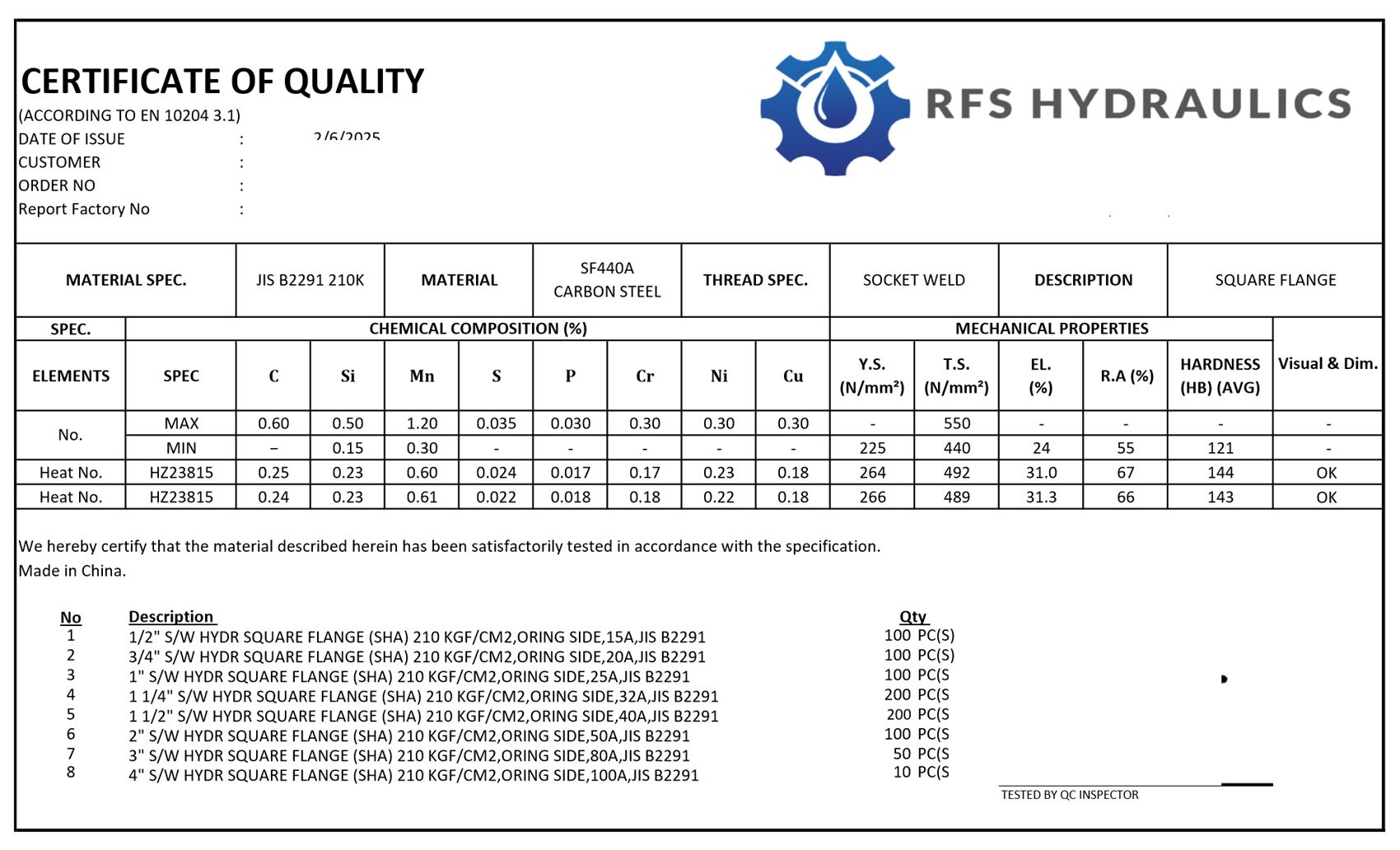
Because we issue it, the heat number on the certificate is the same number stamped on the flange — look back at the marking photo. That is the point of the document: not a declaration that it complies, but a way for you to trace the piece in your hand back to a tested heat.
SF440A, as certified
Specification limits against the figures on the certificate above.
| Chemical composition | C | Si | Mn | S | P | Cr | Ni | Cu |
|---|---|---|---|---|---|---|---|---|
| Specified max | 0.60 | 0.50 | 1.20 | 0.035 | 0.030 | 0.30 | 0.30 | 0.30 |
| Specified min | — | 0.15 | 0.30 | — | — | — | — | — |
| Heat HZ23815 test 1 | 0.25 | 0.23 | 0.60 | 0.024 | 0.017 | 0.17 | 0.23 | 0.18 |
| Heat HZ23815 test 2 | 0.24 | 0.23 | 0.61 | 0.022 | 0.018 | 0.18 | 0.22 | 0.18 |
| Mechanical properties | Yield | Tensile | Elongation | Reduction of area | Hardness | Visual & dim. |
|---|---|---|---|---|---|---|
| Specified min | 225 N/mm² | 440 N/mm² | 24 % | 55 % | 121 HB | — |
| Specified max | — | 550 N/mm² | — | — | — | — |
| Heat HZ23815 test 1 | 264 | 492 | 31.0 | 67 | 144 | OK |
| Heat HZ23815 test 2 | 266 | 489 | 31.3 | 66 | 143 | OK |
Read the heat rows against the specification rows. Yield came in at 264–266 N/mm² against a 225 minimum, tensile at 489–492 inside the 440–550 window, elongation at 31.0–31.3 % against 24 % and reduction of area at 66–67 % against 55 %. Carbon at 0.24–0.25 % sits well under the 0.60 ceiling, which is what keeps the socket weld straightforward, and sulphur and phosphorus are both around half their limits. That is what a 3.1 certificate is for — not to say “it complies”, but to let you check.
Figures are from the certificate reproduced above and describe heat HZ23815 — your order comes with its own certificate and its own heat numbers. Hardness is the average HB.
Look back at the marking photo above. Everything in that table is on the side of the flange, including the heat number. That is the difference between a traceable part and a part that merely arrived with a piece of paper — and it is why we mark our own name on them.
Installing a JIS square flange
Weld first, assemble second — and the order really does matter.
A square flange is a socket weld joint, so unlike a threaded connection the flange is committed to the pipe before the joint is ever made up. That puts most of the risk in the welding stage, not the bolting stage.
The five steps, in order
1. Check the pair first. One A half and one B half, same size and same series. Two of the same letter will not seal, and mixed series will not bolt up.
2. Weld with the O‑ring out. Square the pipe, seat it in the socket and weld round the outside. Never weld with the O‑ring fitted — the heat will destroy it, and a burnt seal is not always obvious afterwards.
3. Clean and inspect. Remove weld spatter and check the face and groove for nicks or contamination. A scratch across the groove is a leak path no amount of torque will close.
4. Seat the O‑ring, then hand tighten. Fit the O‑ring into the groove in the A half, the O‑ring side, bring the halves together and snug all four bolts by hand in a cross pattern. Do not go straight to the torque wrench.
5. Torque evenly, across the diagonal. Work the four bolts up in stages, opposite corners each time, so the O‑ring is compressed squarely rather than pinched at one corner.
On the torque figure itself. Unlike SAE J518, which publishes a bolt torque for every size in both codes, neither JIS B2291 nor JIS F7806 specifies a tightening torque. They fix the flange, the bolt and nut standards and the O‑ring, and stop there. So torque to the bolt — the figure for that thread in SCM435 at the property class your bolt supplier states — not to a number for the flange, and treat any table offering one without naming its source with suspicion. Tell us the thread and we will send the bolt maker’s figure with the order.
Why the square pattern earns its keep
The load is carried by four bolts at the corners rather than one large thread, so the torque per bolt stays modest even at 100A and the joint can be made up properly with a hand torque wrench in a confined space.
Because the seal is an O‑ring in a groove and not a gasket squeezed between flat faces, the joint can be broken and remade many times — replace the O‑ring, inspect the groove and it is good again. There is a single seal point per connection, so there is only one place to look when something weeps.
Blind flanges cap a port for commissioning, pressure testing or a future tie‑in, and use the same bolts and O‑ring as the weld‑in flange at that size.
Watch what a square flange does
Why the joint exists, and where the O‑ring sits.
Why buy square flanges from RFS Hydraulics
Six things that decide whether a flange order goes smoothly.
Ready stock, not ordered in
We hold 1/4" to 6" across the series in Johor Bahru and Singapore rather than buying in against your enquiry, and stock items dispatch the same or next working day.
All three series
210K, 280K and 350K — and both standards, B2291 and F7806. You are not being pushed to the one series a supplier happens to carry.
Complete sets
Both halves, the O‑ring, four bolts and four nuts — with the right bolt length for the type. No arriving on site to find the LSA bolts are 50 mm short.
Weld‑in and blind
Socket weld for the run and blind flanges to close a port off, in every series and both type families.
Marked and traceable
Standard, type, size, series, material and a heat number on the part — with the 3.1 certificate behind it.
The pipe as well
We stock the hydraulic steel tube and SS316 pipe that goes into the socket, so one order covers the joint and the run.
Frequently asked questions
Twelve, from the standards through dimensions and seals to delivery.
What is a square flange used for?
A square flange joins pipe to pipe, or pipe to a component, inside a hydraulic system. The body is square, four bolts pass through the corners, and an O‑ring in a machined groove does the sealing rather than metal‑to‑metal contact. It gives a compact high‑pressure joint that can be broken and remade without disturbing the pipe run.
What is the difference between JIS B2291 and JIS F7806 square flanges?
They are two separate standards. JIS B2291 is the hydraulic square flange standard, used on machinery, presses and mill plant — our 210 kgf/cm² SHA/SHB range is marked to it. JIS F7806 is the shipbuilding standard, written for piping onboard ships and offshore structures, and covers our 280 and 350 kgf/cm² KA/KB ranges. Dimensions and pressure series differ, and halves are not interchangeable between them.
What do 210K, 280K and 350K mean?
The nominal working pressure in kgf/cm² — the legacy label the trade still orders by. The rating the standards state is a round SI figure: 21 MPa (210 bar), 28 MPa (280 bar) and 35 MPa (350 bar). JIS B2291 is titled a 21 MPa flange; JIS F7806 table 1 gives 28 and 35 MPa as the maximum working pressure. So a drawing asking for a hard 21 MPa is met by 210K — do not convert the kgf/cm² label and talk yourself into the next series up.
What does the A or B in SHA, SHB, KA and KB mean?
A is the O‑ring side — the half carrying the machined groove, which our catalogue also calls the counter‑flange. B is the flat side. The two are handed and are ordered as a pair — two of the same letter will not seal against each other. SH, SS, K and LS denote the type family, which goes with the pressure series and the standard.
Can I mix square flange halves from different series?
No. The bolt‑hole centres differ between the series at almost every size — at 25A they are 53, 58 and 65 mm for 210K, 280K and 350K — so the bolts will not line up, and the O‑ring groove differs as well. The exception is 100A, where 210K and 280K share the same 140 mm pitch, the same 190 mm body, so they can be bolted up by mistake. They differ in thickness — C is 55 mm in 210K and 65 mm in 280K — so measure that, or read the marking. Getting it wrong puts a 210 bar flange in a 280 bar line.
How do I identify a square flange I already have?
Read the marking on the side of the flange. The JIS convention is pressure and type, schedule, nominal size, material — for example 280K – A – #160 – 80A – SS400 — which gives you the whole specification. If the marking is gone, measure centre to centre between two adjacent bolt holes and read it off the bolt‑centre table on this page. The old O‑ring also identifies the size, because the JIS B2401 G or P number is fixed per size and series.
Which O-ring does a square flange take?
NBR at HS90 to JIS B2401‑1B, in the G series for most sizes and the P series at 15A in the higher pressure ranges. The size is fixed by the flange, and it is not the same across the series at a given bore: a 50A flange takes a G60 in 210K, a G55 in 280K and a G50 in 350K. Viton (FKM) is available where the fluid or temperature rules out nitrile.
What material are square flanges made from?
SF440A, a forged carbon steel to JIS G3201 — and it is the same grade across all three pressure series. The higher series carry more pressure through heavier sections and larger bolts, not through a different steel. SS316 stainless is available in any series for deck, splash‑zone, chemical or washdown service. In ASTM terms SF440A sits with the SA‑105 SF45 grades.
What bolts and nuts come with a square flange?
Four hex bolts in SCM435 (JIS G4105) and four nuts in S45C (JIS G4051). Thread runs from M10×1.5 at 15A upward, and steps up with the pressure series at the same bore — 65A takes M20 in 210K, M22 in 280K and M24 in 350K. Note the LSA bolt is much longer at the same size, 120 mm against 70 mm at 2B, so standard bolts will not reach on an LSA flange.
Are square flanges and SAE flanges interchangeable?
No, in no size. An SAE J518 flange is round‑bodied, rated in psi classes as Code 61 or Code 62 and dimensioned in inches. A JIS square flange is square‑bodied, rated in kgf/cm² and dimensioned in millimetres against a nominal bore in A sizes. The bolt patterns, the port dimensions and the O‑ring sizes are all different. We stock both lines, so tell us which one the existing installation uses.
What pipe schedule do I need to specify?
The socket bore is machined for the pipe, so the schedule has to be on the order — SCH 40, 80 or 160. At 32A in the 210K series the schedule also changes the O‑ring: SCH 40 takes a G45 and SCH 80 or 160 takes a G40. Send the pipe OD and wall, or the schedule, with the size.
Do you supply blind square flanges?
Yes, in every series and both type families. A blind flange shares the body, the bolt centres and the O‑ring of the weld‑in flange but has no bore, so it closes a port off permanently or during commissioning. Dimensions are in the catalogues on this page.
Catalogues
Direct PDF download — no form, no email address.
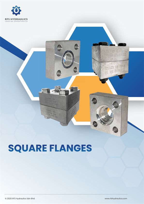
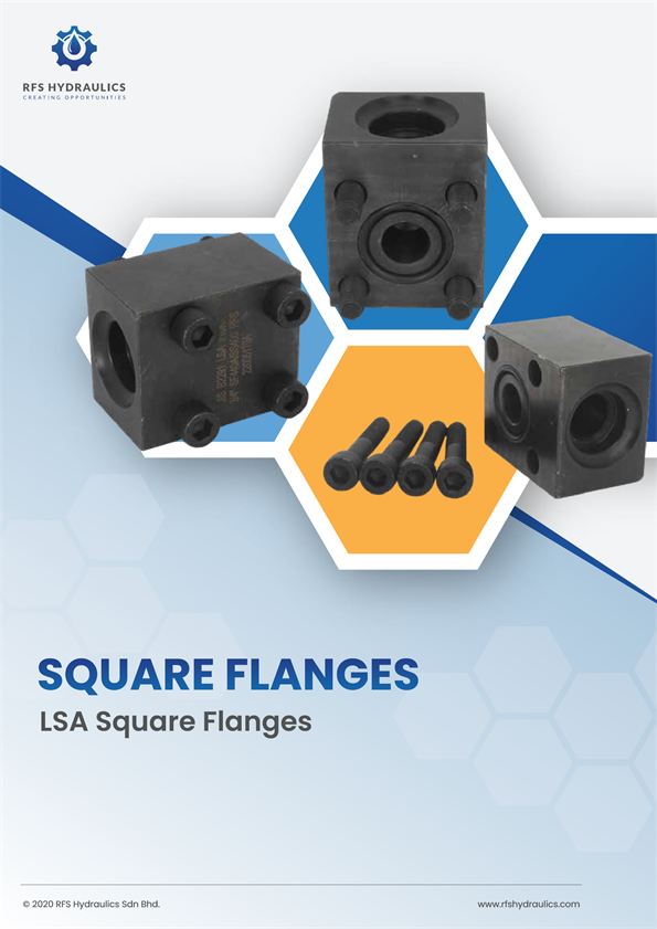
Between them the two catalogues cover weld‑in and blind in all three series, both type families, and the O‑ring groove dimensions for 210K and for 280K/350K. Dimensions and part numbers are in the catalogues; stock and price are not, so send us the list and we will confirm both.
Building the whole joint — the pipe, the seal and the other flange line? Related: all flanges · SAE flanges · O‑rings · hydraulic steel tubes · SS316 pipe · pipe fittings
Send the size, the series and the type letter.
Or a photo of the marking — standard, type, size, series and material are stamped on the side, and we read them off every week. One flange or a full bill of materials, as complete sets with the right bolts, priced by a product specialist within two working hours.