
Home › Products › Flanges › Hydraulic SAE flanges
Oleo Tecnica · ready stockHydraulic SAE flanges to SAE J518 & ISO 6162, 1/2" to 5"
The four‑bolt connection, 1/2" to 5", in Code 61 (3000 series) and Code 62 (6000 series) — up to 414 bar. Carbon steel ST52.3/S355 or stainless SS316L, with NPT, BSPP, socket weld or butt weld ends — as complete sets, split flanges, adaptors and blinds, from stock in Malaysia and Singapore. Working pressure, burst, torque and O‑ring size for every size of both codes, below — straight from SAE J518.
Get a quotation within 2 working hours
Send the part number, standard, size or quantity. Stock in Malaysia or Singapore, ISO 9001:2015 certified.
What an SAE J518 hydraulic flange is, and when you need one
The default four‑bolt connection in hydraulics — and not a variation on the JIS square flange.
An SAE flange joins a tube, pipe or hose end to a port on a pump, motor, valve or manifold, or one half to another in a pipe run. The body is round, the four bolts sit on a rectangular hole pattern either side of the bore, and an O‑ring in a machined face groove does the sealing — not metal‑to‑metal contact. Nothing is threaded into the pressure path, so the joint can be broken and remade without disturbing the run.
You need one when the component has a flat pad with four bolt holes and an O‑ring groove — the pattern is fixed by the pump or the valve, so the port decides the flange. It is also the usual answer at the larger sizes, where a threaded fitting big enough to carry the flow gets hard to tighten in place and hard to seal a second time.
Not the same thing as a JIS square flange
| SAE J518 / ISO 6162 | JIS square flange | |
|---|---|---|
| Body | Round | Square |
| Bolts | Four on a rectangle, either side of the bore | Four through the corners |
| Seal | O‑ring in a face groove | O‑ring in a face groove |
| Rated in | psi classes — Code 61, Code 62 | kgf/cm² — 210 / 280 / 350 |
| Sized in | Inches | Millimetres, nominal bore in A sizes |
| Standard | SAE J518, dimensionally the same connection as ISO 6162 | JIS B2291 hydraulic · JIS F7806 marine |
| Where you meet it | Pump, motor and valve ports worldwide | Japanese and Korean‑built machinery, shipboard and offshore piping |
| Interchangeable | No — not in any size | No — not in any size |
The seal row is the same on both sides, and that is exactly why the two get confused. Everything else differs. We stock both lines — see square flanges.
Specification
Everything that has to be on the enquiry, in one table.
| Property | Specification |
|---|---|
| Size | 1/2" to 5" · DN13 to DN127 · dash −8 to −80 |
| Standard | SAE J518 · ISO 6162 |
| Series | 3000 (Code 61) · 6000 (Code 62) |
| Material | Carbon steel ST52.3 / S355 · stainless SS316L. Galvanised on request |
| Manufacture | Normalised forging in a low‑carbon grade — the actual heat analysis is on the mill certificate supplied with the order |
| End connection | Threaded NPT · threaded BSPP · socket weld (weld in) · butt weld (weld on) |
| Configuration | SAE flange · split flange · flange adaptor · SAE blind flange |
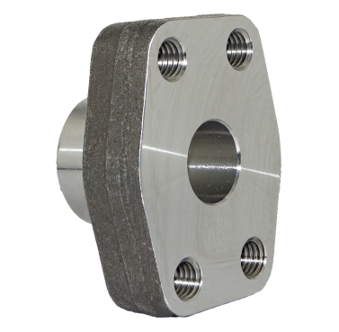
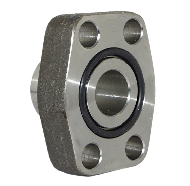
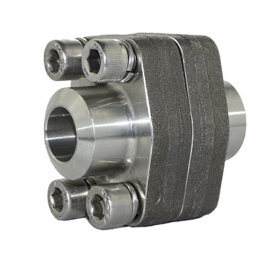
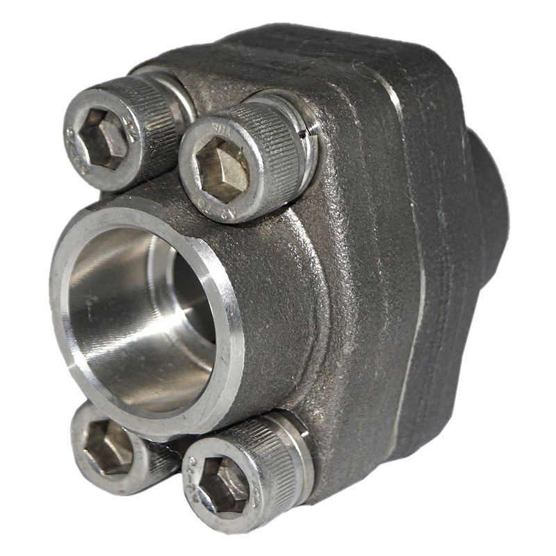
| Complete set | Flat face, O‑ring face, O‑ring, 4 washers and cap screws |
An SAE flange is an alternative to threading a big connection together. It joins pipe, hose, tube or equipment with a leak‑free connection that suits high pressure, larger sizes and assembly in tight quarters — and it has worldwide standard acceptance, which is why the same four‑bolt pattern turns up on machinery from every continent.
The four bolts are the point. Because the load is shared across four cap screws rather than one large thread, the tightening torque per bolt is far lower than an equivalent threaded connection of the same size — which is what makes a 4" connection something one person can make up properly with a hand torque wrench. Ours are Oleo Tecnica.
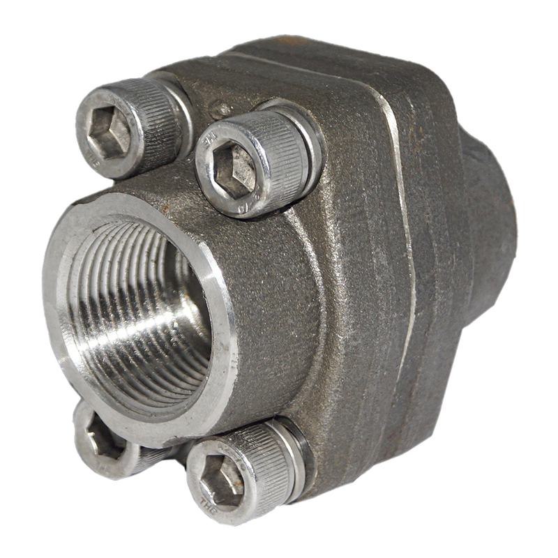
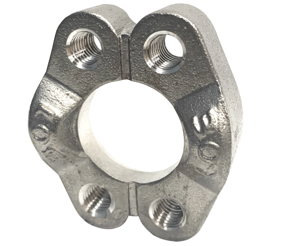
Buying SAE flanges in Malaysia and Singapore
Where the stock sits, what it costs to get it to you, and how fast it moves.
Stock, delivery and ordering
- Where the stock is — the office is in Kuala Lumpur, and flanges are held in two warehouses: Johor Bahru and Singapore, so a Singapore workshop is not waiting on a customs clearance for a common size. Addresses and direct lines are on the contact page.
- Dispatch — stock items leave the same or next working day.
- Delivery within Malaysia — 3 to 5 working days after dispatch. On an urgent stocked item, message us on WhatsApp and say it is urgent.
- Delivery cost — already inside the product price, along with transport, currency conversion, duties and taxes. Nothing is added afterwards.
What moves where. Singapore is mostly shipyard and marine repair — SS316L, Code 62, socket or butt weld, with Viton where the fluid or the temperature calls for it. Malaysia is palm oil mills, construction plant and general industrial hydraulics — mostly carbon steel Code 61 with NBR.
How an SAE flange enquiry runs
Seven things pin a flange down — the first three price it, the rest stop the follow‑up questions:
- Size — 1/2" to 5", the dash size, or the measurement across the bolt‑hole centres.
- Code — 61 or 62. They share sizes but not bolt spacings, so this is the one to get right.
- End connection — NPT, BSPP, socket weld or butt weld.
- Material — ST52.3 or SS316L.
- Seal — NBR or Viton.
- The fluid, and its temperature — they decide the compound, and any derating.
- Configuration — flange, split flange, adaptor or blind.
A product specialist prices it within two working hours. Matching something already fitted? Send a photo with a rule across the bolt centres and we will read the code and the size off it. We also hold the hydraulic steel tube, SS316 tube and fittings the flange connects to.
SAE J518 Code 61 vs Code 62
ISO 6162 defines two series, and pressure is what separates them.
| Code 61 | Code 62 | |
|---|---|---|
| Series | 3000 | 6000 |
| Size range | 1/2" to 5" DN13–DN127 · −8 to −80 | 1/2" to 2" in the standard 2½" and 3" beyond J518‑2 |
| Working pressure | 34 to 345 bar | 414 bar |
| In psi | 500 to 5,000 psi | up to 6,000 psi |
| Construction | Standard | More robust, slightly larger dimensions |
| Seal | O‑ring in a groove | O‑ring in a groove |
Code 61 — the standard pressure series
Flat face, four bolt holes and an O‑ring groove, for lower to moderate pressure. The flat face makes assembly and disassembly straightforward.
Used where moderate pressure ratings are enough: agricultural machinery, construction equipment and general industrial hydraulics. Note the rating falls as size rises — 345 bar at the small end down to 34 bar at 4".
Code 62 — the high pressure series
Same four‑bolt arrangement and O‑ring groove, built for higher pressure — a flat 414 bar across the range, with heavier construction and slightly larger dimensions.
Found where high pressure ratings are required: aerospace, marine and heavy machinery. It stops at 3", so above that you are back to Code 61 or a different connection.
They are not interchangeable. The bolt pattern and port dimensions differ between the two codes, so a Code 62 flange will not mate to a Code 61 port. If you are matching existing equipment, tell us the code — or send a photo with a tape across the bolt centres and we will identify it.
| Can I… | Why | |
|---|---|---|
| Bolt a Code 62 flange to a Code 61 port? | No | The bolt‑hole centres are further apart at every size — 40.49 × 18.24 mm against 38.10 × 17.48 mm at 1/2", and the gap widens as the size goes up. The screws will not line up. |
| Fit a Code 61 half against a Code 62 half? | No | Same reason, plus the port dimensions and screw sizes differ. Halves are only interchangeable within one code and one size. |
| Run a Code 62 flange at Code 61 pressure? | Yes | A higher‑rated flange on a lower‑pressure line is not a problem — but it will not mate to a Code 61 port, so this only applies if the whole joint is Code 62. |
| Use a Code 61 flange at Code 62 pressure? | No | Compare 21 MPa against 42 MPa at 2". It is half the rating, and half the burst margin with it. |
| Mix metric and inch screws in one flange? | No | SAE J518 treats them as two types with different screws, lengths and torques. A metric‑screw port is marked M; an inch port is not. |
| Reuse the O‑ring? | No | Replace it every time the joint is broken. It costs almost nothing next to the downtime. |
Which code should I start from?
| The duty | Start from | Why |
|---|---|---|
| General industrial, agricultural and construction hydraulics | Code 61, carbon steel | The standard series — but its rating falls with size, so check the table below |
| High pressure across the whole size range | Code 62 | Flat 414 bar — and it stops at 3" |
| Marine decks, shipyard and washdown | Code 62 in SS316L | What Singapore shipyards actually order — with Viton where the fluid or temperature calls for it |
| Large bore at modest pressure | Code 61 at 3½"–5" | 35 bar up there — a large connection, not a high pressure one |
| Matching an existing port | Whatever the port is | The pattern is fixed by the pump or valve — identify it first |
Start from, not order from. Final selection is the size row in the pressure table below, the temperature rows in the materials section, and the O‑ring compound against the fluid. Send the duty and we confirm all three before you commit.
Working pressure and burst, size by size
The whole of SAE J518 Table 1A, because the rating is not one number.
Code 61 does not hold one pressure across the range — and this is where most specifying mistakes happen. The rating starts at 35 MPa and steps down as the size grows, then drops off a cliff at 3½". Code 62 by contrast is flat at 42 MPa across every size the standard tabulates. Minimum burst pressure is four times the working pressure throughout, which is the standard’s own safety factor.
Series 3000 · Code 61 · metric screws, class 10.9
| Dash | Size | DN | Screw | Screw length | Min thread | Torque | Max working pressure | Min burst |
|---|---|---|---|---|---|---|---|---|
| −8 | 1/2" | 13 | M8 | 25 mm | 16 mm | 32 Nm | 35 MPa · 350 bar | 140 MPa |
| −12 | 3/4" | 19 | M10 | 30 mm | 18 mm | 70 Nm | 35 MPa · 350 bar | 140 MPa |
| −16 | 1" | 25 | M10 | 30 mm | 18 mm | 70 Nm | 32 MPa · 320 bar | 128 MPa |
| −20 | 1¼" | 32 | M10 | 30 mm | 18 mm | 70 Nm | 28 MPa · 280 bar | 112 MPa |
| −24 | 1½" | 38 | M12 | 35 mm | 23 mm | 130 Nm | 21 MPa · 210 bar | 84 MPa |
| −32 | 2" | 51 | M12 | 35 mm | 23 mm | 130 Nm | 21 MPa · 210 bar | 84 MPa |
| −40 | 2½" | 64 | M12 | 40 mm | 23 mm | 130 Nm | 17.5 MPa · 175 bar | 70 MPa |
| −48 | 3" | 76 | M16 | 50 mm | 30 mm | 295 Nm | 16 MPa · 160 bar | 64 MPa |
| −56 | 3½" | 89 | M16 | 50 mm | 30 mm | 295 Nm | 3.5 MPa · 35 bar | 14 MPa |
| −64 | 4" | 102 | M16 | 50 mm | 30 mm | 295 Nm | 3.5 MPa · 35 bar | 14 MPa |
| −80 | 5" | 127 | M16 | 55 mm | 30 mm | 295 Nm | 3.5 MPa · 35 bar | 14 MPa |
Read the last three rows before you design anything large in Code 61. From 3½" upward the rating is 3.5 MPa — 35 bar, an order of magnitude below the 1/2" figure. A 4" Code 61 flange is a large connection, not a high pressure one. If you need size and pressure, the answer is Code 62 up to 2", or a different connection entirely — talk to us before the drawing is released.
Series 6000 · Code 62 · metric screws, class 10.9
| Dash | Size | DN | Screw | Screw length | Min thread | Torque | Max working pressure | Min burst |
|---|---|---|---|---|---|---|---|---|
| −8 | 1/2" | 13 | M8 | 30 mm | 16 mm | 32 Nm | 42 MPa · 420 bar | 168 MPa |
| −12 | 3/4" | 19 | M10 | 35 mm | 18 mm | 70 Nm | 42 MPa · 420 bar | 168 MPa |
| −16 | 1" | 25 | M12 | 45 mm | 23 mm | 130 Nm | 42 MPa · 420 bar | 168 MPa |
| −20 | 1¼" | 32 | M12 | 45 mm | 23 mm | 130 Nm | 42 MPa · 420 bar | 168 MPa |
| −24 | 1½" | 38 | M16 | 55 mm | 27 mm | 295 Nm | 42 MPa · 420 bar | 168 MPa |
| −32 | 2" | 51 | M20 | 70 mm | 35 mm | 550 Nm | 42 MPa · 420 bar | 168 MPa |
2½" and 3" Code 62 sit outside SAE J518‑2’s table. We stock them — M24 and M30 screws respectively, rated 414 bar by the manufacturer — but the figures come from Oleo Tecnica’s own documentation rather than from the SAE table, and we will say so on the quotation. Ask for the certificate if the duty is critical.
All figures above are SAE J518‑1 and SAE J518‑2, issued January 2013, Table 1A (Type 1, metric screw, class 10.9). Minimum burst is the standard’s working pressure × 4. The flange is one of three ratings in the joint — the tube or pipe and the port have their own, and the lowest of the three governs the line.
How to identify a flange you already have
Four checks with a tape and a torch, before you order the wrong thing.
1 · Measure across the bolt‑hole centres
This single measurement gives you both the size and the code. Take it centre‑to‑centre on the long side of the four‑hole rectangle, then read it off the table below. The two codes are only 2–3 mm apart at the small sizes, so measure properly — a steel rule beats a tape.
2 · Look for the letter M
SAE J518 requires a port made for metric screws to be permanently marked M, at least 3 mm tall, on the centreline between the bolt holes and clear of the O‑ring sealing area. A port for inch screws carries no mark at all. So an M means metric; no M means inch, or a port made to an older edition of the standard.
3 · Find the maker’s mark
The standard says the flange head should carry the manufacturer’s name or trademark as a minimum. If there is no mark anywhere on the head, you are looking at an unbranded part and its rating is unknown — which matters more than the price you paid for it.
4 · Read the O‑ring
The AS568 dash number is fixed per size and is the same for both codes — 210 at 1/2", 219 at 1", 228 at 2". If you still have the old O‑ring, it confirms the size even when the flange is too corroded to measure cleanly. The full list is in the O‑ring section.
Bolt‑hole centres, both codes
Centre to centre, in millimetres. Long side × short side of the four‑hole rectangle.
| Size | Code 61 · 3000 | Code 62 · 6000 | Difference |
|---|---|---|---|
| 1/2" | 38.10 × 17.48 | 40.49 × 18.24 | +2.4 |
| 3/4" | 47.63 × 22.23 | 50.80 × 23.80 | +3.2 |
| 1" | 52.37 × 26.19 | 57.15 × 27.76 | +4.8 |
| 1¼" | 58.72 × 30.18 | 66.68 × 31.75 | +8.0 |
| 1½" | 69.85 × 35.71 | 79.38 × 36.50 | +9.5 |
| 2" | 77.77 × 42.88 | 96.82 × 44.45 | +19.1 |
| 2½" | 88.90 × 50.80 | 123.80 × 58.70 | +34.9 |
| 3" | 106.38 × 61.93 | 152.40 × 71.40 | +46.0 |
| 3½" | 120.65 × 69.85 | — | — |
| 4" | 130.18 × 77.77 | — | — |
| 5" | 152.40 × 92.08 | — | — |
Watch the 3" and 5" trap. A 3" Code 62 and a 5" Code 61 share the same 152.40 mm long dimension. They are nothing like each other — different bore, different screws, 420 bar against 35 bar — so check the short dimension too, and the bore, before you decide. Dimensions above are from Oleo Tecnica’s catalogue for the range we stock.
Still not sure? Send a photo with a rule laid across the bolt centres and the bore visible, to info@rfshydraulics.com or on WhatsApp. We identify these every week and it takes a minute.
Bolt torque, both codes
The numbers that decide whether the O‑ring seals or extrudes.
Torque is not optional detail on an SAE flange — it is the sealing mechanism. The cap screws are tightened to a specified torque, and that compression is what squeezes the O‑ring into its groove to form a complete seal around the connection. It also pulls the faces into even contact, which is what stops a leak path opening at one corner. Under‑torque and it weeps; over‑torque and the O‑ring extrudes and the screws yield.
Series 3000 · Code 61
| Flange size | Screw thread | Screw torque (Nm) |
|---|---|---|
| 1/2" | M8 | 32 |
| 3/4" | M10 | 70 |
| 1" | M10 | 70 |
| 1 1/4" | M10 | 70 |
| 1 1/2" | M12 | 130 |
| 2" | M12 | 130 |
| 2 1/2" | M12 | 130 |
| 3" | M16 | 295 |
| 3 1/2" | M16 | 295 |
| 4" | M16 | 295 |
| 5" | M16 | 295 |
Series 6000 · Code 62
| Flange size | Screw thread | Screw torque (Nm) |
|---|---|---|
| 1/2" | M8 | 32 |
| 3/4" | M10 | 70 |
| 1" | M12 | 130 |
| 1 1/4" | M12 | 130 |
| 1 1/2" | M16 | 295 |
| 2" | M20 | 550 |
| 2 1/2" | M24 | 550 |
| 3" | M30 | 650 |
Recommended torque values. Compare the two tables at the same size — a 2" Code 61 takes M12 at 130 Nm, while a 2" Code 62 takes M20 at 550 Nm. Using the Code 61 figure on a Code 62 flange will not seal it. Bolt grade also matters: torque figures assume the grade supplied.
| Also from the standard | What it means on the bench |
|---|---|
| Torque assumes lubricated screws | SAE J518 states its torque figures are a guide for lubricated screws, calculated at a coefficient of friction of 0.17. Net tightening torque changes with lubrication, coating and surface finish — which is the real reason the screw finish matters. |
| Snug all four first | The standard carries an explicit caution: lightly torque every screw before applying the final value, or the flange clamp can break during installation. Work across the pattern, not around it. |
| Hardened washers | Recommended, because of the surface pressure between the screw head and the clamp. Older flanges made to earlier editions of J518 / ISO 6162 may not have room for them. |
| Installation procedure | SAE J2593 is the installation standard J518 refers you to. |
| Inch screws | J518 marks the Type 2 (inch screw) assemblies “not for new design”. They remain available for maintaining existing equipment; specify metric (Type 1) for anything new. |
Source: SAE J518‑1 and SAE J518‑2, issued January 2013, Table 1A and the accompanying notes.
Bolt grades supplied
What comes as standard, and what to ask for.
| Bolt grade | Finish / material | Supplied |
|---|---|---|
| 8.8 | Yellow zinc | Standard with carbon steel flanges |
| 10.9 | FIZn 240h L | On request — a higher‑strength screw, zinc coated and rated 240 h salt spray before red rust |
| SS304 | Stainless | Standard with stainless steel flanges |
| SS316 | Stainless | On request — higher corrosion resistance |
The flange has through holes and the mating half is tapped — in UNC or metric thread. On the pair, the flat face mounting holes are tapped and the O‑ring face holes are not, which is the quickest way to tell the two halves apart on a bench.
ST52.3 or SS316L?
Strength and weldability, against corrosion resistance.
Steel ST52.3 / S355
A low alloy, high tensile strength structural steel with good weldability and machinability — which is why it is the default for hydraulic components.
Choose it where the flange has to withstand high pressure and mechanical stress and corrosion is not the governing concern. Galvanising is available if the run is exposed.
Stainless AISI SS316L
The low carbon variant of SS316, a molybdenum‑bearing austenitic stainless. Excellent corrosion resistance.
Choose it for harsh environments and high moisture exposure — marine decks, washdown areas, chemical plant — where corrosion resistance is critical and longevity matters more than material cost.
Note the bolts change with it: SS304 comes as standard, SS316 on request.
Carbon steel or SS316L, side by side
The temperature rows are from SAE J518, not from us.
| Carbon steel ST52.3 / S355 | Stainless SS316L | |
|---|---|---|
| Strength | Higher tensile — the default for hydraulic duty | Lower tensile than the steel, ample for the rated pressures |
| Corrosion resistance | Needs the coating to survive; galvanising on request | Molybdenum‑bearing austenitic — resists chlorides and washdown |
| Weldability | Good — butt weld and socket weld both routine | Good, low carbon limits sensitisation at the weld |
| Standard screws | 8.8 yellow zinc | SS304 standard, SS316 on request |
| Temperature at the table pressures SAE J518 | −40 °C to +120 °C below −20 °C, ask before assembly | −60 °C to +50 °C below −20 °C, ask before assembly |
| Derating above +50 °C SAE J518 | None stated up to +120 °C | −4 % above +50 to <+100 °C −11 % +100 to <+200 °C −20 % +200 to +250 °C |
| Choose it when | Pressure and mechanical stress govern and corrosion is controlled | Marine decks, washdown, chemical plant — where life beats material cost |
This is the row people get wrong. Temperature capability belongs to the flange material and the O‑ring compound — not to the screw plating. A hot line is a case for the right material and a Viton seal, not for a different bolt finish.
Corrosion protection the standard actually requires
Useful when you are comparing quotes on price alone.
| Part | Requirement in SAE J518 |
|---|---|
| Carbon steel flanges except weld‑on heads | Plated or coated to pass a 72 h salt spray test to ASTM B117 / ISO 9227. Any red rust is a failure, apart from internal fluid passages, thread crests, hex points and areas deformed after plating. |
| Weld‑on flange heads | 16 h neutral salt spray, protected by oil film or phosphate — deliberately light, so weldability is not harmed. |
| Screws and washers | 16 h salt spray, phosphate coated with an oil finish unless otherwise agreed. J518’s torque values were derived on exactly that finish. |
| Not permitted | No cadmium plating. Hexavalent chromate coatings are not preferred for commercial and industrial use. |
O-rings: NBR or Viton?
A static face seal, and the fluid decides which compound.
The O‑ring is what seals an SAE flange — not the metal. Metal‑to‑metal contact at the outer face of the flange will leak, so a high durometer O‑ring is compressed between the flat face and the O‑ring face to give a reliable soft seal that contains the pressurised fluid. Getting the compound right for the fluid matters as much as getting the torque right.
| NBR 70/90 | Viton 90 | |
|---|---|---|
| Equivalent | BUNA‑N | FKM |
| Temperature range | −34 °C to 121 °C | −26 °C to 205 °C |
| Recommended for | Petroleum oils and fluids · cold water · diesel fuel and fuel oils · mineral oil and grease · vegetable oil · silicone oil and grease | Petroleum oils and fluids · cold water · silicone greases and oils · aromatic and aliphatic hydrocarbons · fuels with methanol content |
| Not recommended for | Aromatic hydrocarbons · phosphate ester fluids · strong acids · automotive brake fluid | Ammonia gas, amines, alkalis · low molecular organic acids · superheated steam · glycol based brake fluids |
The clearest split is aromatic hydrocarbons. They are on NBR’s not recommended list and on Viton’s recommended list — so if the fluid contains them, Viton is the answer. Viton also buys you 84 °C more at the top end. Watch the traps though: neither compound suits glycol‑based or automotive brake fluid, and Viton is wrong for superheated steam. Tell us the fluid and the temperature and we will specify the compound. See also O‑rings.
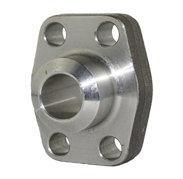
Which O‑ring does my size take?
Straight from SAE J518 — and the same O‑ring serves both codes at the same size.
| Dash | Flange size | DN | O‑ring size AS568 | Code 61 | Code 62 |
|---|---|---|---|---|---|
| −8 | 1/2" | 13 | 210 | ✓ | ✓ |
| −12 | 3/4" | 19 | 214 | ✓ | ✓ |
| −16 | 1" | 25 | 219 | ✓ | ✓ |
| −20 | 1¼" | 32 | 222 | ✓ | ✓ |
| −24 | 1½" | 38 | 225 | ✓ | ✓ |
| −32 | 2" | 51 | 228 | ✓ | ✓ |
| −40 | 2½" | 64 | 232 | ✓ | — |
| −48 | 3" | 76 | 237 | ✓ | — |
| −56 | 3½" | 89 | 241 | ✓ | — |
| −64 | 4" | 102 | 245 | ✓ | — |
| −80 | 5" | 127 | 253 | ✓ | — |
Before you reuse a flange, look at the groove. SAE J518 sets the sealing surface at Ra max 3.2 µm and rules that scratches wider than 0.13 mm running across the bore or the bottom and outside of the O‑ring groove are not acceptable. Circumferential tool marks within the roughness limit are fine. A scratch you can catch a fingernail in is a leak path — replace the half.
Approvals and documentation
What is available, and what a flange certificate actually covers.
Flanges are forged rather than rolled, so the material documentation follows the forging: an EN 10204 3.1 certificate reporting the chemical analysis and mechanical tests for the lot. Tell us what the job needs when you enquire — on classed marine and offshore work the paperwork requirement is usually set by the client, not by us.
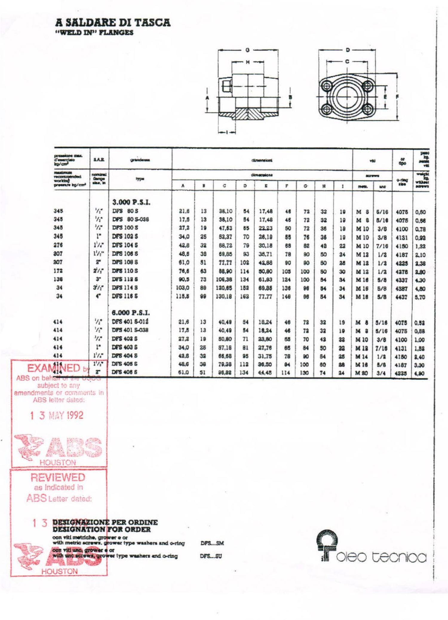
Read the pressure column, not just the size. It is the single most common mistake on SAE flanges: people assume a rating applies across a series when in the 3000 series it drops by a factor of ten between the smallest and largest sizes. If you are working near a limit, ask us to confirm the figure for the exact size and code before you order.
Why two sets of numbers? The 1992 ABS document above quotes the older psi‑derived series — 345, 276, 207, 172, 138 and 34 bar, being 5,000 down to 500 psi. The January 2013 edition of SAE J518 states the same ratings in MPa — 35, 32, 28, 21, 17.5, 16 and 3.5 MPa. They agree within rounding at most sizes and differ by a step at 1" and 3". The size‑by‑size tables on this page follow the 2013 standard; where a job is close to a limit we quote against the specific part and its documentation, not against a generic series figure.
Who makes them
Because “equivalent to” is not a manufacturer.
The flanges we stock are made by Oleo Tecnica S.r.l. of Treviglio, Bergamo, Italy — a flange machine shop, not a general trader. That matters for two reasons. It is a named, traceable source, so the ABS type examination above and the conformance and material documents all point at the same maker rather than at whichever mill was cheapest that month. And SAE J518 itself requires the flange head to carry the manufacturer’s name or trademark as a minimum — a flange with no mark on it is a flange with no rating you can stand behind.
Conformance certificates, the tensile‑strength conformance statement and the third‑party audit documentation for the range are available on request — tell us at enquiry stage what your client needs to see and we will send it with the quotation rather than after the order.
Installing an SAE flange: four steps
Zero‑clearance assembly, and the order matters.
An SAE flange gives a zero‑clearance assembly — easy to connect, disconnect and maintain, whether the joint is tube to hose, tube to tube or a manifold connection. Infinite positioning is built in, so the flange can sit at any angle rather than being fixed by a thread.
The four steps
- 1. Inspect. Check the component surfaces for damage or contamination. A nick across the O‑ring groove is a leak path that no amount of torque will close.
- 2. Align and seat. Align the connection, insert the O‑ring into the female flange groove, then place the washers and cap screws through the bolt holes.
- 3. Hand tighten the cap screws to seat the O‑ring on the groove. Do not go straight to the torque wrench.
- 4. Torque to the value for that size and code — see the torque tables.
Why split flanges earn their keep
Connections have to come apart eventually to replace or service system components. A split flange is two halves clamped around a flange adaptor, so the joint breaks without rotating the pipework — which on a fabricated run is the difference between a ten minute job and cutting the line.
That is the fourth advantage of the design, alongside connecting up to 5", a single seal point per connection, and much lower bolt torque than an equivalent threaded flange.
Blind flanges cap a port for commissioning, testing or a future tie‑in.
Watch the flange go together
SAE flange assembly, step by step.
Why buy SAE flanges from RFS Hydraulics
Six things that decide whether a flange order goes smoothly.
Ready stock, not ordered in
We stock across 1/2" to 5" in Johor Bahru and Singapore rather than buying in against your enquiry, and stock items dispatch the same or next working day.
Both codes, both materials
Code 61 and Code 62 in ST52.3 and SS316L, so the code and the material are design choices rather than whatever the supplier happens to hold.
Complete sets, not just flanges
Flat face, O‑ring face, O‑ring, four washers and cap screws together — so nothing is missing when the fitter opens the box.
All four end connections
NPT, BSPP, socket weld and butt weld, plus split flanges, adaptors and blinds. Specified at enquiry, not improvised on site.
Torque data published
Full bolt torque tables for both codes are on this page, along with the O‑ring compound guide. You can plan the assembly before the parts arrive.
The tube and fittings as well
We stock the hydraulic steel tube, compression fittings and pipe clamps the flange connects to. More about RFS Hydraulics.
Delivery within Malaysia is already inside the price. See the FAQ or the terms and conditions.
Frequently asked questions
Twelve, from the codes through torque and seals to delivery.
What is a hydraulic SAE flange?
A four‑bolt flange conforming to SAE J518 and ISO 6162, used to connect hydraulic components — hoses, pipes, tubes, valves and pumps. It gives a leak‑free connection that suits high pressure, larger sizes and assembly in tight quarters. A complete set is the flat face, the O‑ring face, the O‑ring, and four washers and cap screws.
What is the difference between Code 61 and Code 62 flanges?
Pressure. Code 61 is the 3000 series standard pressure range: 1/2" to 5" at 34–345 bar (500–5,000 psi). Code 62 is the 6000 series high pressure range: 1/2" to 3" at 414 bar (up to 6,000 psi), with more robust construction and slightly larger dimensions. Both use a flat face, four bolt holes and an O‑ring groove. They are not interchangeable — the bolt patterns differ.
What torque do SAE flange bolts need?
It depends on the size and the code — full tables for both are on this page. As an example, a 2" Code 61 takes M12 at 130 Nm, while a 2" Code 62 takes M20 at 550 Nm. Torque is the sealing mechanism: it compresses the O‑ring into its groove and pulls the faces into even contact. Hand tighten to seat the O‑ring first, then torque.
Which O-ring should I use, NBR or Viton?
NBR 70/90 (BUNA‑N) covers −34 °C to 121 °C and suits petroleum oils, cold water, diesel and fuel oils, mineral oil and grease. Viton 90 (FKM) covers −26 °C to 205 °C and additionally suits aromatic and aliphatic hydrocarbons and fuels with methanol — all of which are on NBR’s not‑recommended list. Neither suits glycol‑based or automotive brake fluid, and Viton is wrong for superheated steam. Tell us the fluid and temperature.
What material are SAE flanges made from?
Normalised forging, from base steel with carbon below 0.30%. Two grades: carbon steel ST52.3 / S355, a low alloy high tensile structural steel with good weldability and machinability; and stainless AISI SS316L, the low carbon molybdenum‑bearing austenitic grade for harsh or high‑moisture environments. Galvanised is also available.
What bolt grades come with the flanges?
Grade 8.8 in yellow zinc is standard with carbon steel flanges, and SS304 is standard with stainless flanges. On request: grade 10.9 (FIZn 240h L) where a higher‑strength screw is specified, and SS316 for higher corrosion resistance.
How are SAE flanges attached to pipe?
Four end connections: threaded NPT, threaded BSPP, socket weld (weld in) and butt weld (weld on). Welded and threaded ends both maximise reliability — the choice is usually driven by whether the run is fabricated or screwed. Specify the end at enquiry.
What is a split flange for?
It is two halves clamped around a flange adaptor, so the joint can be broken without rotating the pipework. Since connections have to come apart eventually to service or replace components, a split flange turns that into a quick job instead of cutting the line. We also supply flange adaptors and blind flanges for capping a port during commissioning or a future tie‑in.
Can Code 61 and Code 62 flanges be interchanged?
No. The bolt‑hole centres differ at every size — 38.10 × 17.48 mm for Code 61 at 1/2" against 40.49 × 18.24 mm for Code 62 — and the gap widens with size, reaching 19 mm at 2". The screws simply will not line up, and the port dimensions and screw sizes differ as well. You cannot mix halves across codes either. A Code 62 joint can of course run at low pressure, but a Code 61 flange must never be used at Code 62 pressure — at 2" that is 21 MPa against 42 MPa, half the rating and half the burst margin. See the bolt‑hole centre table if you are measuring an existing flange.
How do I identify an SAE flange I already have?
Four checks. Measure centre to centre across the long side of the four bolt holes — that one dimension gives you the size and the code together. Look for the letter M between the bolt holes: SAE J518 requires a port made for metric screws to be marked with an M at least 3 mm tall, while a port for inch screws carries no mark. Find the manufacturer’s name or trademark on the flange head, which the standard says should be there as a minimum. And read the old O‑ring — the AS568 dash number is fixed per size and is the same for both codes. Full tables are in the identification section. If it is easier, send us a photo with a rule laid across the bolt centres.
Can SAE flanges be reused?
Yes, provided they are undamaged and properly inspected at reassembly. Check the O‑ring groove and both faces for nicks or contamination before refitting, and replace the O‑ring rather than reusing it — the seal is the consumable, the flange is not.
Are SAE flanges compatible with different hydraulic fluids?
The flange itself works with a wide range — mineral oil, synthetic fluids and water‑based fluids. The limiting part is the O‑ring, not the metal, so fluid compatibility is really a question of choosing NBR or Viton. See the seal compatibility table.
Catalogues
Three SAE flange catalogues. Direct PDF download — no form, no email address.
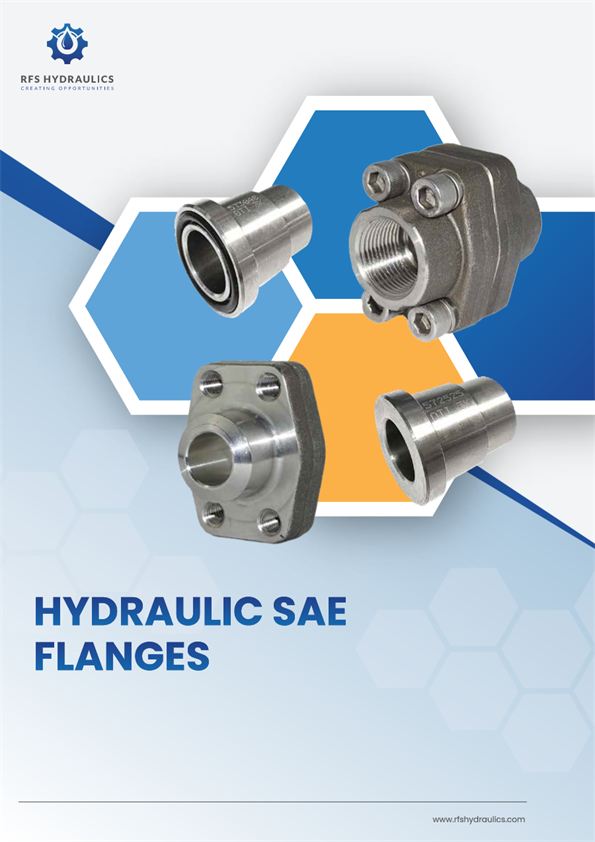 Hydraulic SAE flangesRFS Hydraulics · PDFPDF
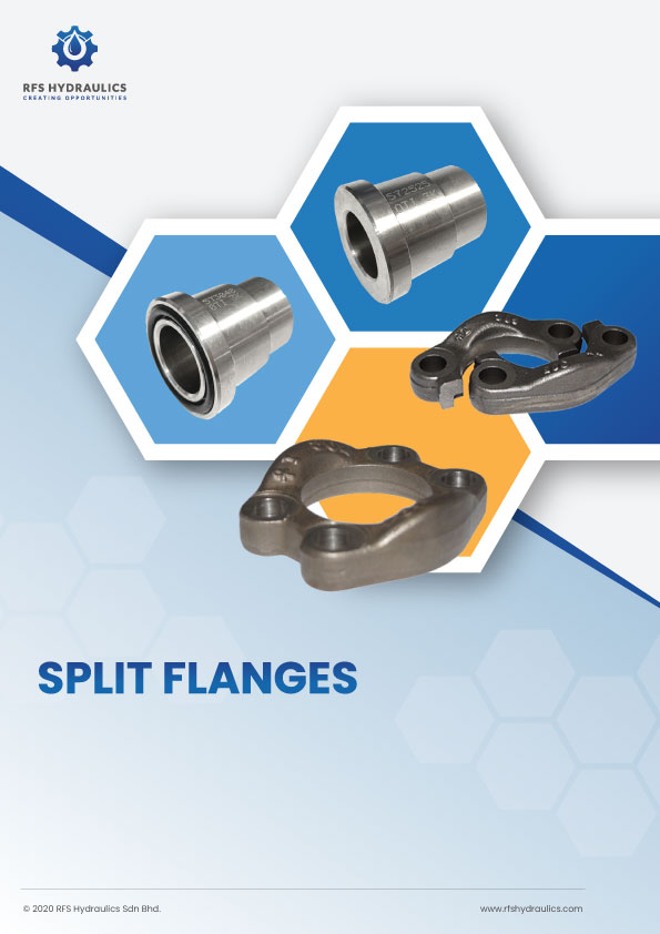 SAE split flangesRFS Hydraulics · PDFPDF
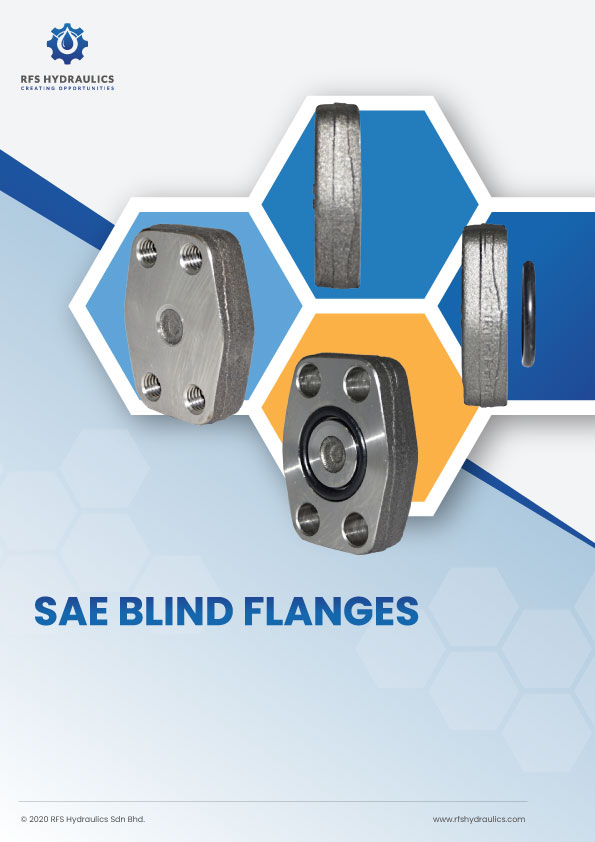 SAE blind flangesRFS Hydraulics · PDFPDF
Dimensions and part numbers are in the catalogues; stock and price are not, so send us the list and we will confirm both.
Building the whole joint — the seal, the tube and the other flange line? Related: all flanges · square flanges · O‑rings · bonded seals · hydraulic steel tubes · about Oleo Tecnica
Send the size, the code and the end connection.
One flange or a full bill of materials — we confirm the code against the port, the pressure against the size, and the seal against the fluid, then price it. Not sure what is fitted? Send a photo with a rule across the bolt centres. A product specialist answers within two working hours.